TGW Route Tables
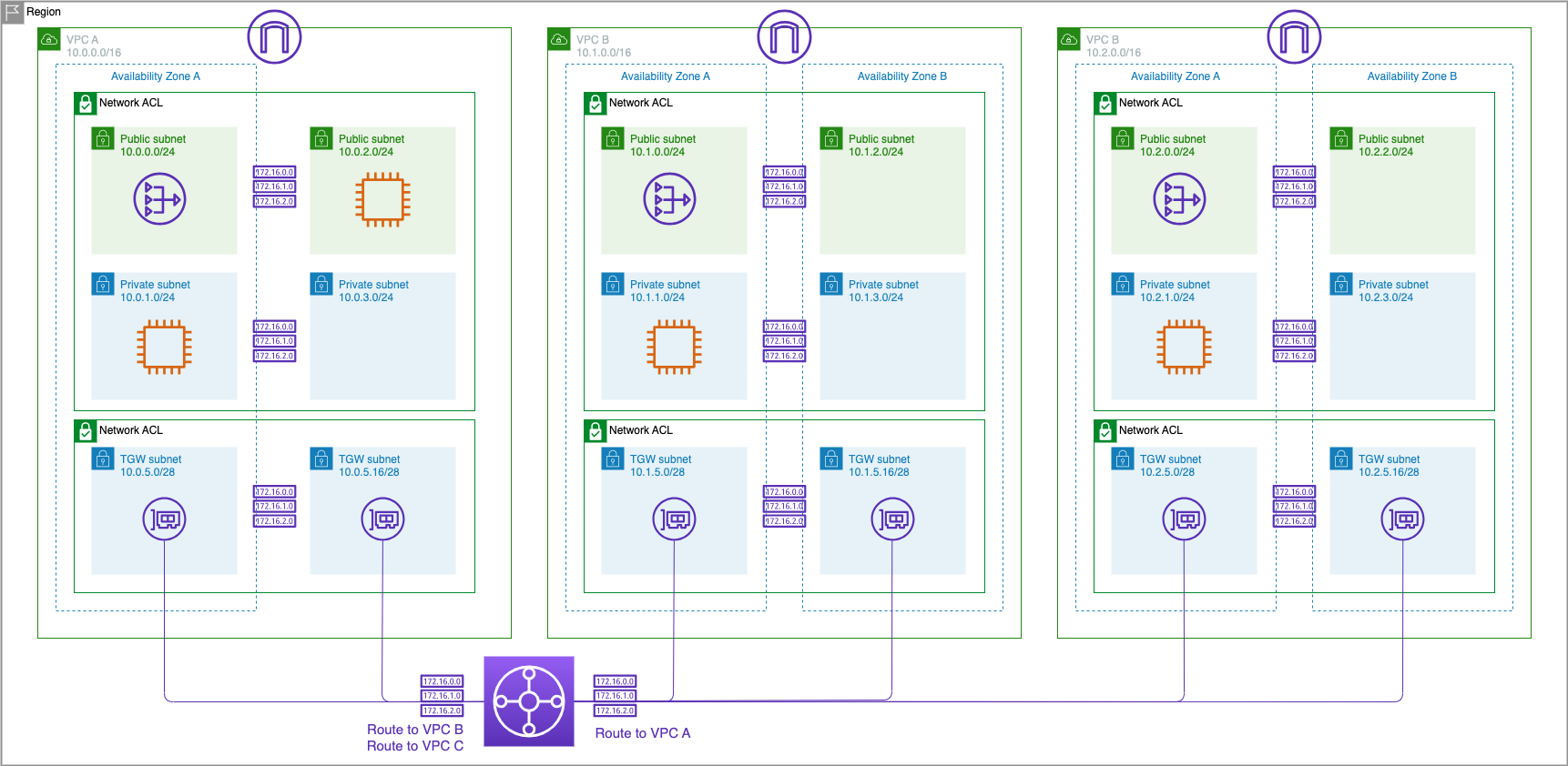
Your transit gateway routes IPv4 and IPv6 packets between attachments using transit gateway route tables. You can configure these route tables to propagate routes from the route tables for the attached VPCs, VPN connections, and Direct Connect gateways. You can also add static routes to the transit gateway route tables. When a packet comes from one attachment, it is routed to another attachment using the route that matches the destination IP address.
In this section we will explore using transit gateway route tables to provide network segmentation.
Inspect the Transit Gateway Default Route Table
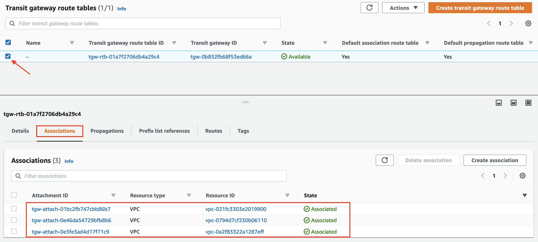
- In the VPC Dashboard scroll down and click Transit Gateway Route Tables
- Select the Transit Gateway route table, scroll down and click on the Associations Tab. You will see the three attachments for the three VPCs.
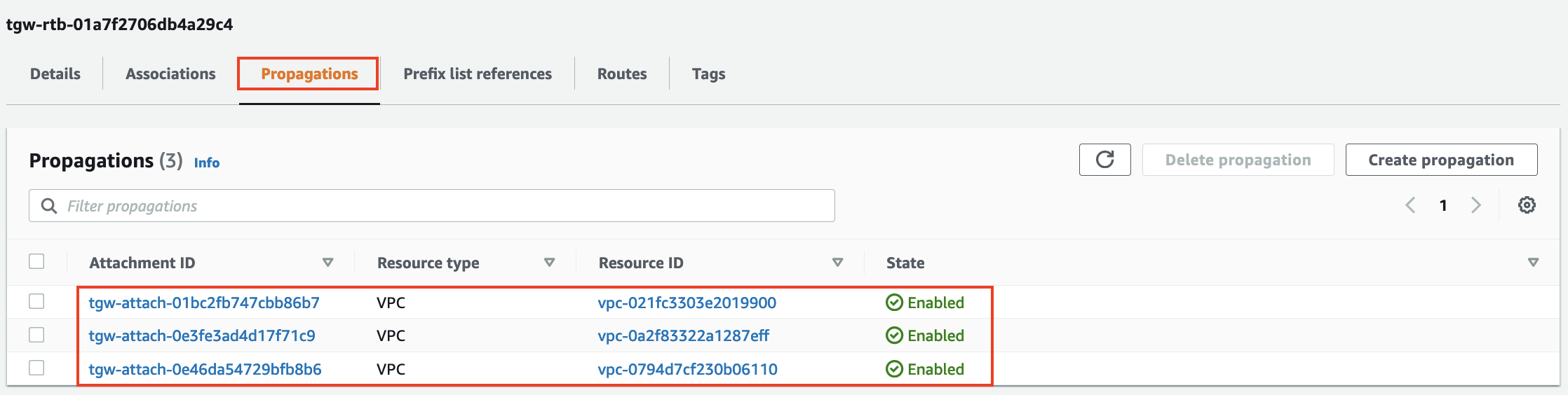
- Next click on the Propagations Tab. You will see all three attachments are propogating the CIDRs for the VPCs.
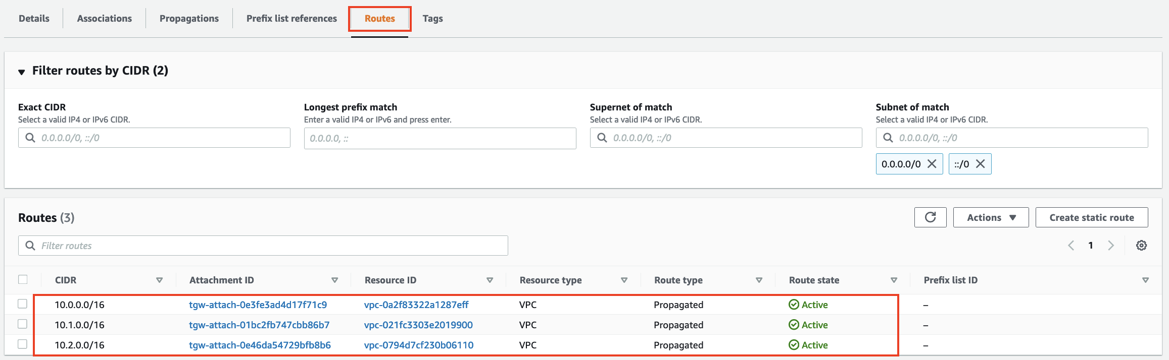
- Finally click on the Routes Tab. You will see the three routes for the three VPCs.
As we have seen the Transit Gateway automatically associates newly attached VPCs to the default route table and propagates routes from the VPCs into the Transit Gateway Route Table. This makes it very easy for VPCs to have connectivity to other VPCs.
But there are often times when we do not want VPCs to have connectivity to other VPCs except for a Shared Services VPC. For this lab we will use VPC A as our Shared Services VPC and modify the default configurations on the Transit Gateway route table and make it so that VPC B and VPC C cannot talk to each other but both are able to communicate with any shared services in VPC A.
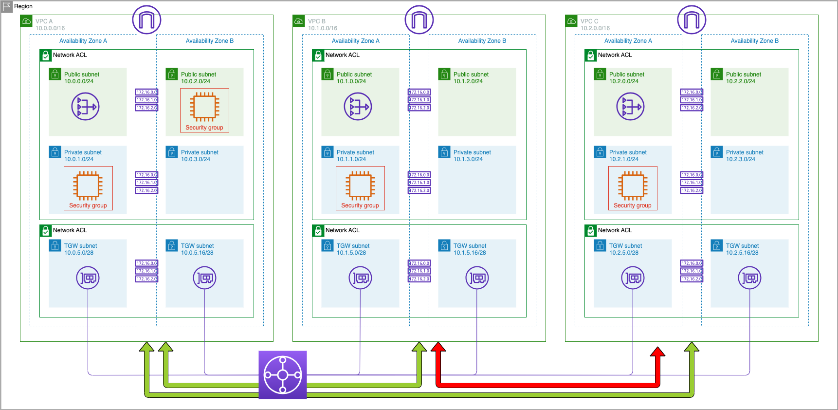
This is a typical ‘shared services’ VPC configuration in which VPC A would host services like LDAP, DNS, or other shared resources.
Delete VPC A Attachment from Transit Gateway Route Table
The first thing we need to do is delete the association for VPC A from the original Transit Gateway Route Table that you created. You need to reference the VPC ‘Resource ID’ to ensure you delete the correct VPC
- Navigate to Your VPCs and make a note of the VPC ID for VPC A.

- Navigate back to Transit Gateway Route Tables
- Select the check box for the TGW route table and scroll down to the Associations tab
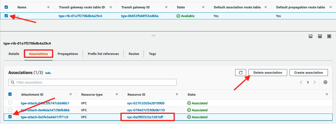
- Select the association with the Resource ID that matches the VPC ID for VPC A noted down earlier and click Delete association
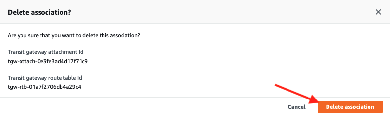
- Confirm the deletion by clicking Delete Association on the following screen
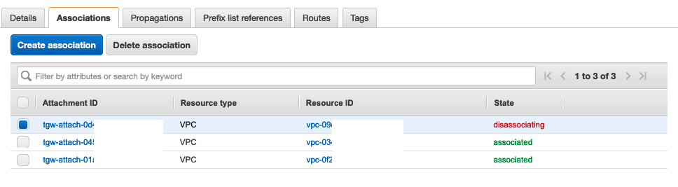
- The association will move into disassociating state.
Delete Propagations for VPC B & C from Transit Gateway Route Table
We will now delete the propagations that were automatically created for both VPC B and VPC C one at a time from the route table so that the only one remaining is that for the VPC ID of VPC A. This will remove the routes for VPC B and VPC C so they cannot reach each other via this route table.
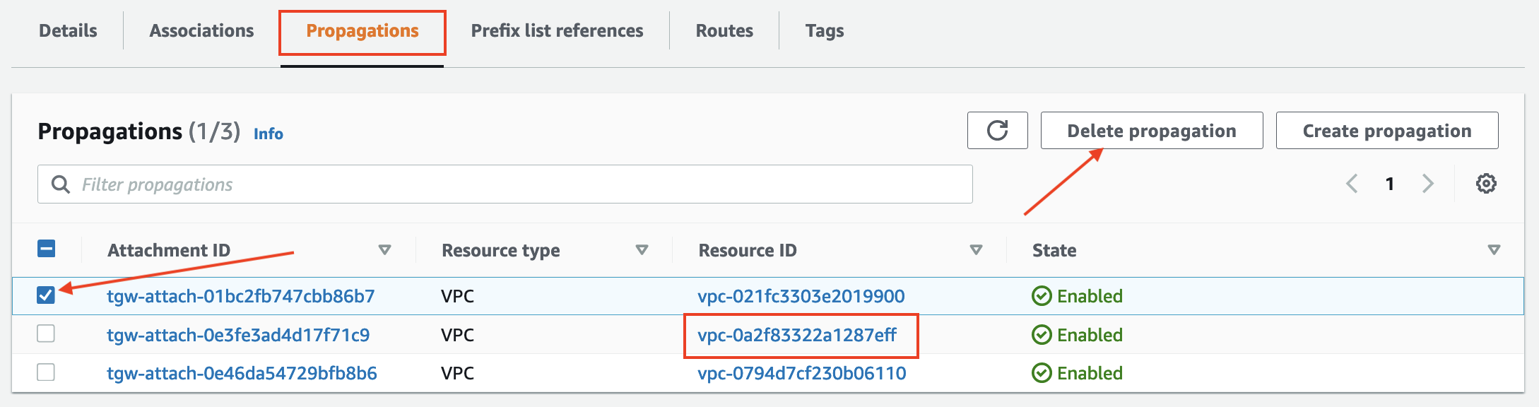
- Navigate to the Propagations tab.
- Select one of the propagations where the Resource ID does NOT match the VPC ID noted down for VPC A and click Delete Propagation
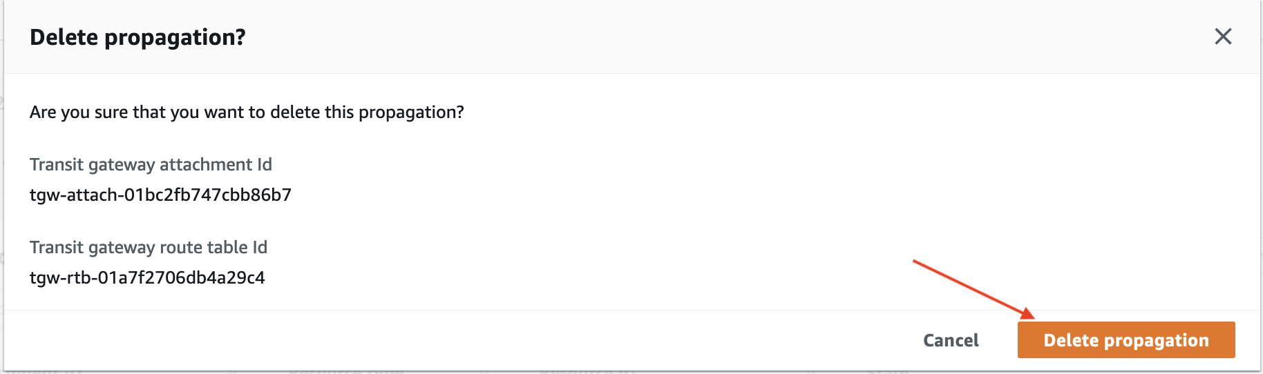
- Confirm the deletion by clicking Delete propagation on the pop-up.
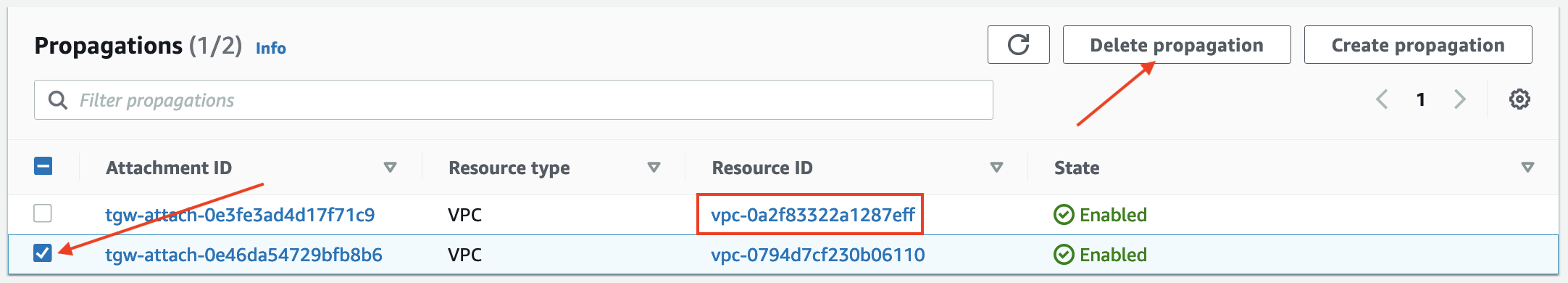
- Select the other propagation where the Resource ID does NOT match the VPC ID for VPC A and click Delete Propagation
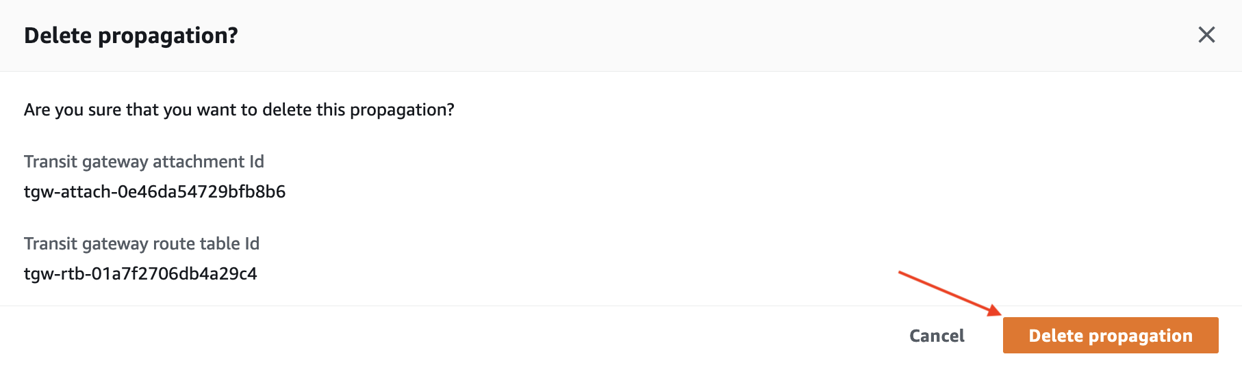
- Confirm the deletion by clicking Delete propagation on the pop-up.
- Navigate to the Routes tab to check the result (it may take a few seconds to update)
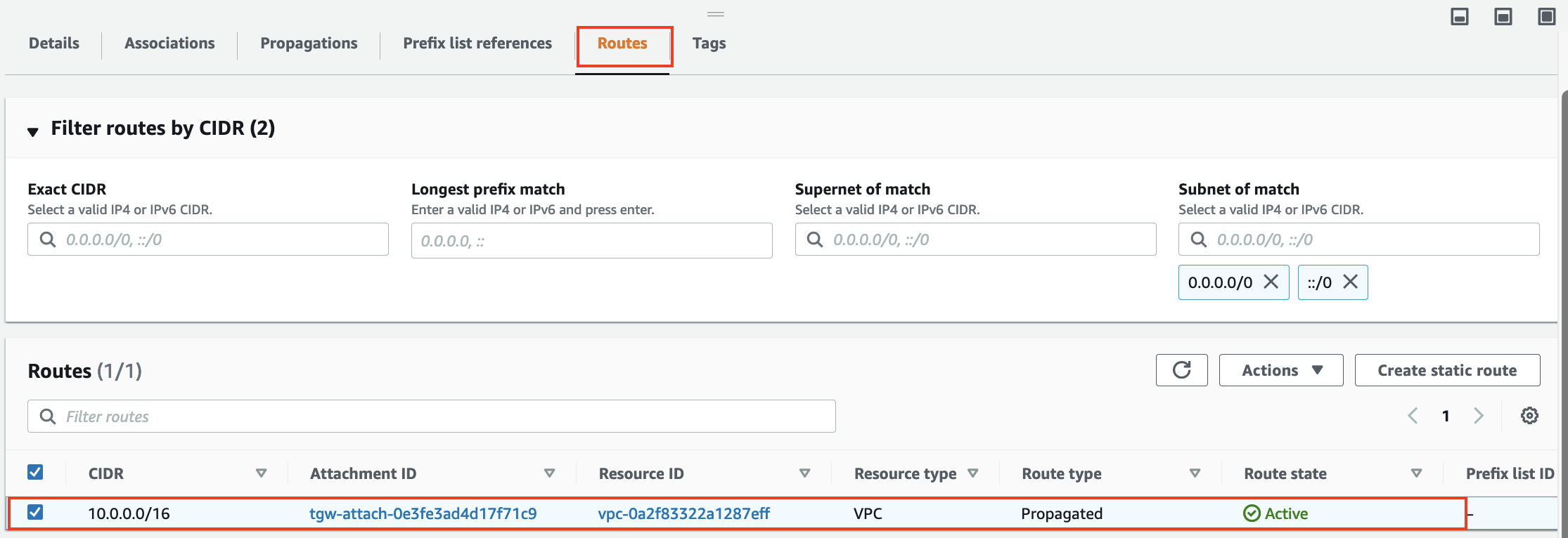
The only route in the original Transit Gateway Route Table should be a propagated route to 10.0.0.0/16 to VPC A.
The attachments for both VPC B and VPC C are still associated to the original route table and this means that both VPC B and VPC C are able to reach VPC A via the route table as there is a route for 10.0.0.0/16 being propagated into it by VPC A.
However the attachment for VPC A is no longer associated to a route table in the TGW and therefore there is no routing information that would allow traffic to reach VPC B and VPC C from VPC A. To add those routes we will now create another route table for VPC A to use.
Create Shared Services Route Table
To create a return path from VPC A we will create a new Shared Services Route Table.
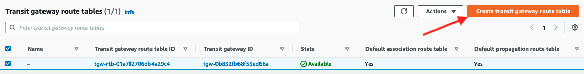
- Click Create Transit Gateway Route Table
- Enter
Shared Services TGW Route Tableas the Name tag and select the transit gateway from the dropdown for Transit Gateway ID
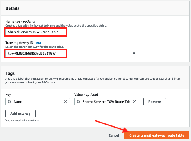
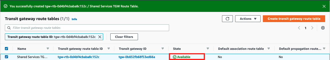
- Click Create transit gateway route table and wait for the new route table to change state to available*
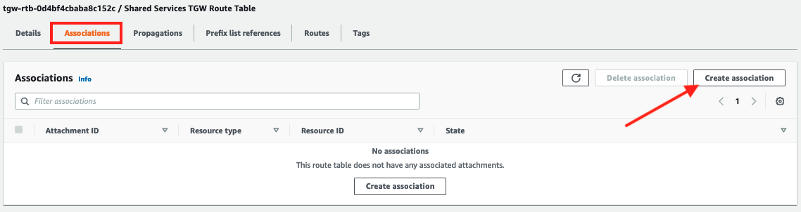
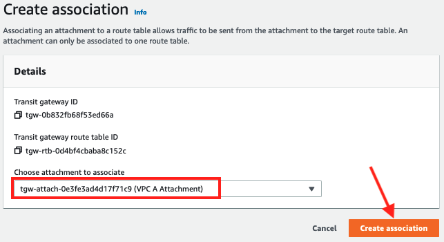
- Scroll down to the Associations tab and click Create association
- Associate the
VPC A attachmentwith the Shared Services route table by selecting it from the dropdown and clicking Create association.
Create Propagations for VPC B & VPC C
Now that VPC A is associated with the new Shared Services Route Table in the Transit Gateway we need to create propagations for VPC B and VPC C so that this route table knows how to access 10.1.0.0/16 and 10.2.0.0/16. This enables VPC A to have a return path to both VPC B and VPC C.
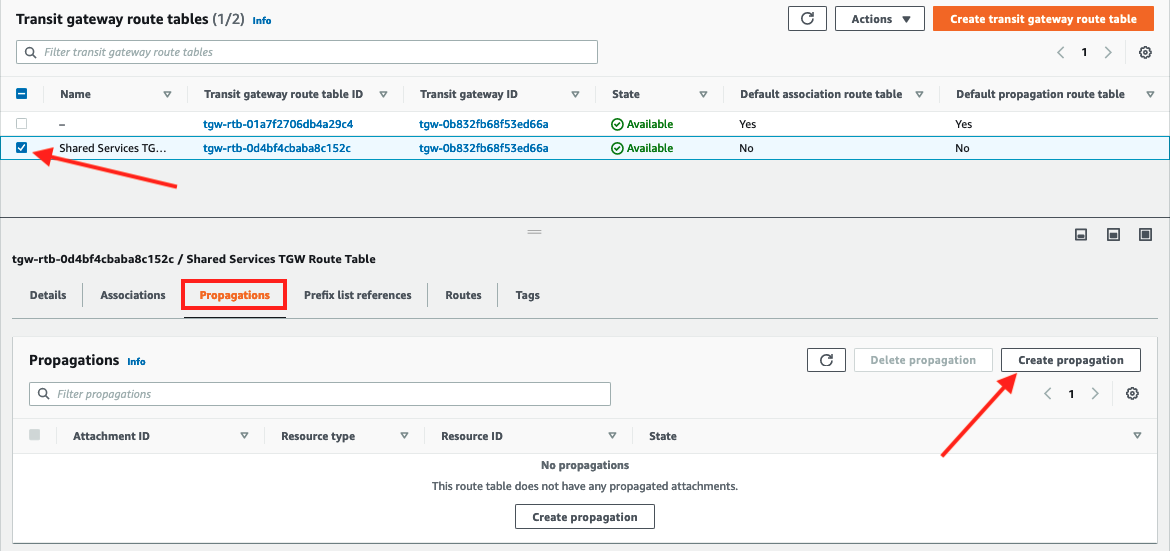
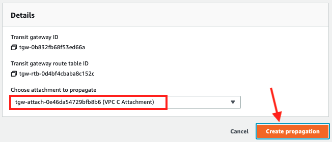
- Navigate to Propagations tab and click Create Propagation.
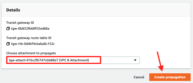
- Select the
VPC B attachmentfrom the dropdown and click Create propagation
- Repeat the process to add a propagation for VPC C so there are two propagations in the Propagations tab
- There should now be two propagations in the Propagations tab
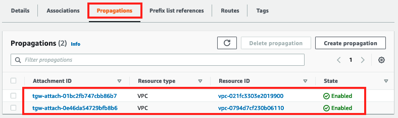
- Take a look at the Routes tab for the shared services route table.
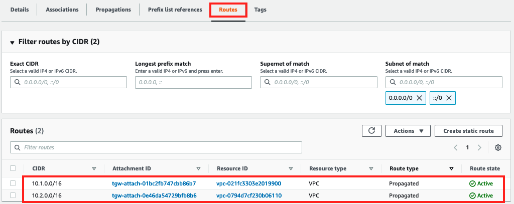
There should be routes to both VPC B (10.1.0.0/16) and VPC C (10.2.0.0/16).
Test Connectivity
Now let’s use Session Manager to connect to the EC2 instance in VPC B and test connectivity to the instances in VPC A and VPC C.
- In the EC2 Dashboard click on EC2 Instances
- Select
VPC B Private AZ1 Serverand Click Connect - In the Session Manager tab, click Connect
- Ping the servers in VPC A
10.0.1.100and VPC C10.2.1.100
ping 10.0.1.100 -c 5
ping 10.2.1.100 -c 5
sh-4.2$ ping 10.0.1.100 -c 5
PING 10.0.1.100 (10.0.1.100) 56(84) bytes of data.
64 bytes from 10.0.1.100: icmp_seq=1 ttl=254 time=1.002 ms
64 bytes from 10.0.1.100: icmp_seq=2 ttl=254 time=0.909 ms
64 bytes from 10.0.1.100: icmp_seq=3 ttl=254 time=0.908 ms
64 bytes from 10.0.1.100: icmp_seq=4 ttl=254 time=0.896 ms
64 bytes from 10.0.1.100: icmp_seq=5 ttl=254 time=0.903 ms

--- 10.0.1.100 ping statistics ---
5 packets transmitted, 5 received, 0% packet loss, time 4004ms
rtt min/avg/max/mdev = 0.896/1.128/2.024/0.448 ms
sh-4.2$ ping 10.2.1.100 -c 5
PING 10.2.1.100 (10.2.1.100) 56(84) bytes of data.

--- 10.2.1.100 ping statistics ---
5 packets transmitted, 0 received, 100% packet loss, time 4072ms

sh-4.2$
Now because we deleted the association in the main route table VPC B can talk to VPC A, but VPC B cannot talk to VPC C.
Congratulations you've established network segmentation using the Transit Gateway route tables and completed the lab.