Catalyst 8000v Autonomous Mode Deployment with AWS TGW Connect
This guide will walk you through the process of configuring a Catalyst 8000v router in AWS and manually connecting to AWS Transit Gateway with a TGW Connect Attachment using GRE
Prerequisites
Note: These are provided in dCloud, but will be needed if configuring in your own account
- Access to vManage interface
- C8Kv device list already uploaded to vManage
- AWS account with appropriate permissions
- Access and Secret keys for AWS account
Configuration Steps
Step 1: Create Transit VPC
First, you will need to create a Transit VPC in which to host the Cat8Kvs. For this design, we will create a VPC with 2 availability zones and 4 subnets, but other designs are possible.
-
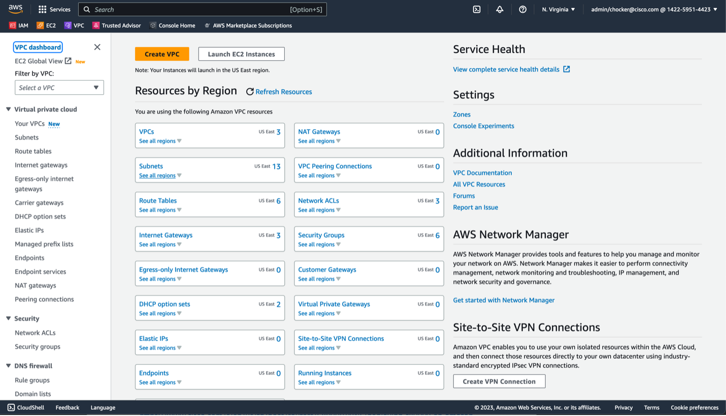
In the AWS console, open the VPC dashboard
-
Use the "Create VPC" wizard at the top
-
Configure VPC settings
We will use public subnets for the WAN/on-prem facing subnets. Public subnets are subnets with a default route to an IGW. If you are using direct connect, the WAN subnets will probably be private subnets. Select the following options:
- Choose VPC and more
- Name the VPC transit
- Use the appropriate CIDR block, probably at least a /24
- For this example, we will not use IPv6, but it is an option
- Select Tenancy and use default
- Select 2 AZs
- Select 2 public subnets
- Select 2 private subnets
- Choose None for NAT Gateways and VPC endpoints
- Enable DNS hostnames and DNS resolution
- Click Create VPC
You should see the following results:
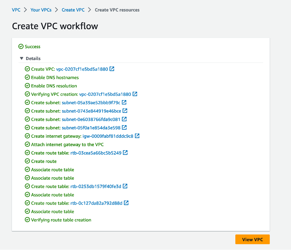
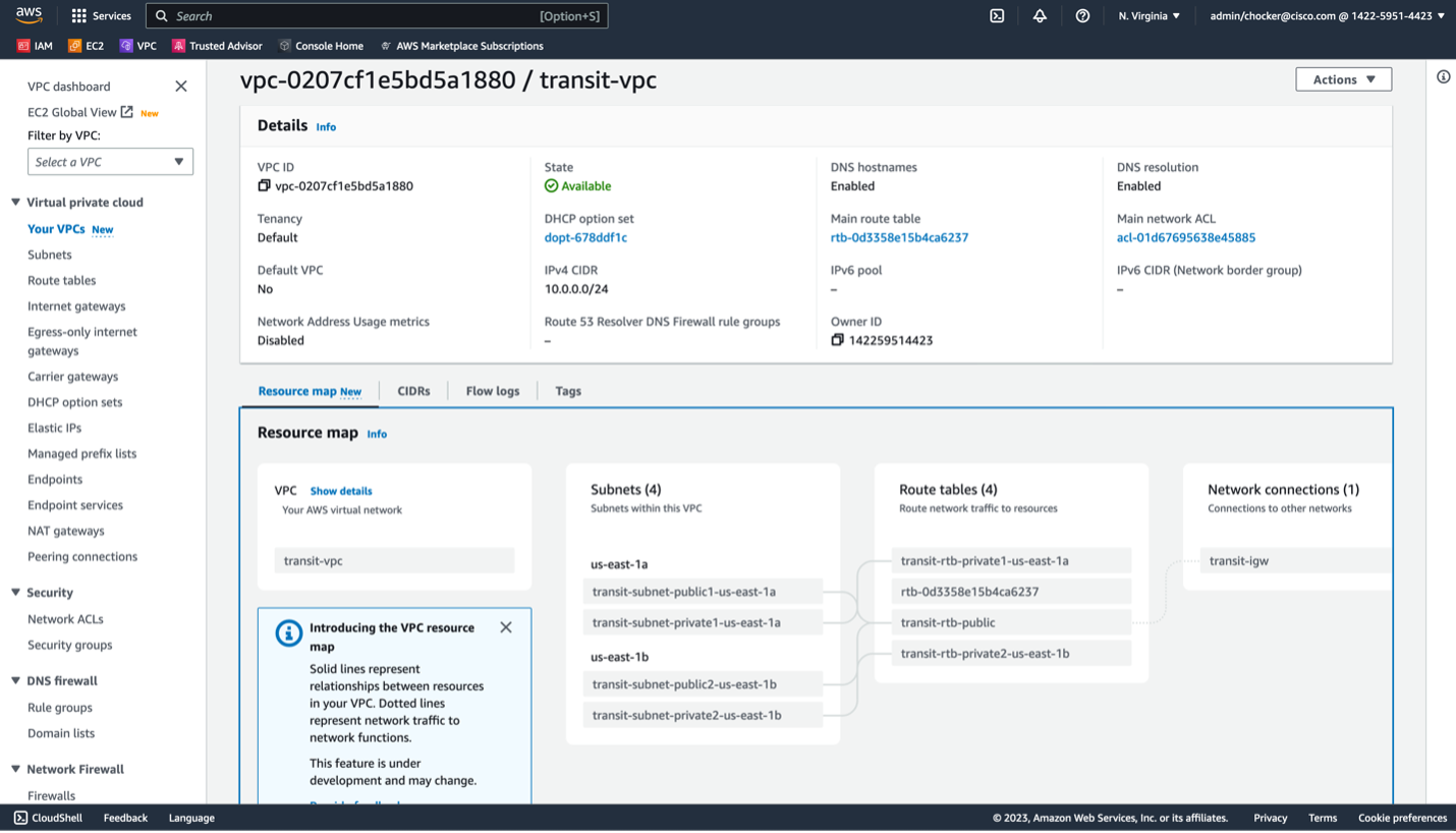
Click View VPC and you should see something like this output.
Step 2: Deploy Cat8Kv into Transit VPC
-
Follow the instructions for the Cisco documentation on deploying a C8Kv from the AWS Marketplace
C8000v Marketplace Subscription
For this deployment guide, we will use a t3.medium instance type, BYOL licensing, and the latest IOS-XE release.
-
In the Choose Action step, it is suggested to use Launch through EC2 as it provides the necessary level of customization
-
Suggested settings include
- Chose a SSH keys that you want to use for CLI access to the router (or create a new pair)
- Disable auto assign public IP
- Choose the new created transit VPC
- Select one of the public subnets
- Create a security group called cat8kv-wan that at a minimum allows SSH access from whatever subnets are appropriate
-
Open Advanced Network configuration, and input the following
- For Network Interface 1, call it WAN in the description
- Optional, statically assign the IP address in the WAN subnet
- Optional, select delete on termination if desired
- Click Add Network Interface
- For Network Interface 2, call it TGW in the description
- Choose the private subnet
- Optional, statically assign the IP address
- Optional, select delete on termination if desired
-
You can use the defaults for all the remaining settings
-
Launch the instance
-
Browse the EC2 dashboard, and under Network and Security options on the left-hand side options, choose Elastic IPs and click allocate Elastic IP on the next screen
-
Go back to the EC2 dashboard and select the newly created Cat8Kv. Browse to the Networking Tab and click on the WAN network interface
-
Click the box next to the interface to select it, and then under actions choose associate address and assign the newly created elastic IP address
-
You should now be able to SSH to the Cat8Kv using the ec2-user username, the configured SSH keys, and the elastic IP address. For example
ssh -i "your-8kv-ec2.pem" ec2-user@ec2-3-214-37-35.compute-1.amazonaws.com -
Configure a hostname
ip-10-0-0-13#conf t Enter configuration commands, one per line. End with CNTL/Z. ip-10-0-0-13(config)#hostname cat8kv-1 -
Enable the Gig2 interface and configure it for DHCP
cat8kv-1(config)#interface GigabitEthernet 2 cat8kv-1(config-if)#no shut cat8kv-1(config-if)#ip address dhcp -
Check that Gig2 received an IP address
cat8kv-1#show ip int br Interface IP-Address OK? Method Status Protocol GigabitEthernet1 10.0.0.13 YES DHCP up up GigabitEthernet2 10.0.0.140 YES DHCP up up VirtualPortGroup0 192.168.35.101 YES TFTP up up -
Configure both interfaces for 10GE speed
cat8kv-1(config)#interface GigabitEthernet 1 cat8kv-1(config-if)#no negotiation auto cat8kv-1(config-if)#speed 10000 cat8kv-1(config)#interface GigabitEthernet 2 cat8kv-1(config-if)#no negotiation auto cat8kv-1(config-if)#speed 10000 -
Configure Gig2 to match the TGW Connect MTU
cat8kv-1(config)#interface GigabitEthernet 2
cat8kv-1(config-if)#mtu 8500
Note: Eventually, we will need to create additional Cat8Kvs for redundancy and scale out performance. For this guide, we are going to create just one and integrate it to the TGW. Additional Cat8Kvs can be created using the same steps.
Step 3: Create the TGW
For the next few sections, the AWS Transit Gateway documentation is a good reference. https://docs.aws.amazon.com/vpc/latest/tgw/tgw-getting-started.html
If this is a greenfield deployment, you will now create a TGW. Otherwise, if you are using an existing TGW you may need to update the TGW to add a CIDR block.
- Navigate to the VPC dashboard, and on the left-hand side bar under the Transit Gateways section select Transit Gateways.
- Select Create Transit Gateway.
- Selection the following options
- Name and description based on whatever is appropriate.
- Assign an ASN to the TGW. It most cases this should be a private assign. In this example we will use 65001.
- Assign a /24 CIDR block. This will be used for the TGW connect attachment. It probably does not need be unique to the environment as it only used to terminate the GRE tunnels used between Cat8Kvs and TGW as part of the TGW connect attachment.
- The rest of the default options are fine.
- Click Create Transit Gateway.
Note: It can take a few minutes before the TGW is fully created and available. It should eventually move from an initial state of Pending to Available. When available you can move onto the next step.
Step 4: Create VPC Attachment from TGW to the Transit VPC
We now need to create a VPC attachment from the TGW to the Transit VPC. This provides the necessary underlay transport path that is needed for the TGW connect attachment.
- Navigate to the VPC dashboard, and on the left-hand side bar under the Transit Gateways section select Transit Gateway Attachments.
- Selection Create transit gateway attachment.
- Use the following options:
- Name it transit-vpc-attachment
- Select the Transit GW
- Attachment Type is VPC
- For VPC ID, select the Transit VPC
- Attach to the private subnets in each VPC.
- The rest of the options can be default.
- Click Create transit gateway attachment.
Again, this may take a few minutes to complete. It should eventually move from an initial state of Pending to Available. When available you can move onto the next step.
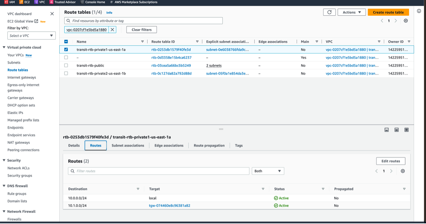
- Navigate to the VPC dashboard and under the Virtual Private Cloud section select Route Tables.
- For each of the private subnet route tables in the Transit VPC, add a route for the TGW CIDR block that points to TGW attachment as the target.
Step 5: Create TGW Connect Attachment from the TGW to the Cat8Kv
The TGW Connect attachment provides the direct peering of the Cat8Kv and the TGW.
- Navigate to the VPC dashboard, and on the left-hand side bar Under the Transit Gateways section select Transit Gateway Attachments.
- Selection Create transit gateway attachment.
- Use the following options:
- Name it transit-vpc-connect
- Select the Transit GW.
- Attachment Type is Connect.
- For Transport attachment ID, select the VPC attachment created in the previous step.
- Click Create transit gateway attachment.
Note: Again, this may take a few minutes to complete. It should eventually move from an initial state of Pending to Available. When available you can move onto the next step.
Step 6: Create TGW Connect Peers from the TGW to the Cat8Kv
Now we will create GRE tunnels between the TGW and Cat8Kv. Over each GRE tunnel a BGP session is established to provide dynamic routing. Dynamic routing is important for ECMP load balancing, path preferencing, and failover.
Note: Each GRE tunnel has a throughput limit of 5 Gbps.
Note: Each TGW has a limit of 1,000 routes it will accept from the Cat8Kv. Route summaries on the Cat8Kv may be needed if the Cat8Kv BGP routing table size exceeds the capacity of the TGW.
- Navigate to the VPC dashboard, and on the left-hand side bar Under the Transit Gateways section select Transit Gateway Attachments.
- Click on the hyperlink under the Transit Gateway Attachment ID for the TGW connect attachment that was created in the previous step.
- Navigate to the Connect Peers.
- Click Create Connect Peer.
- User the following options:
- For name, give to EC2 instance name of the Cat8Kv. For example, cat8kv-1.
- Optional, leave the Transit gateway GRE address blank or assign one from the TGW CIDR block. This is the IP address that will be used to terminate the GRE tunnel on the TGW.
- The Peer GRE address should the IP address of the Cat8Kv network interface 2, the interface in the Transit VPC TGW subnets.
- The BGP inside CIDR block IPv4 needs to be a/29 subnet in the 169.254.0.0/16 range. There are some blocks within this range that AWS does not allow, so check the TGW connect documentation if needed. We will use the 169.254.10.0/29 in this example.
- Peer ASN should be the ASN of the Cat8Kv. In this example we use 65000.
- Click Create connect peer.
- Navigate back to the TGW connect attachment and select the connect peers tab.
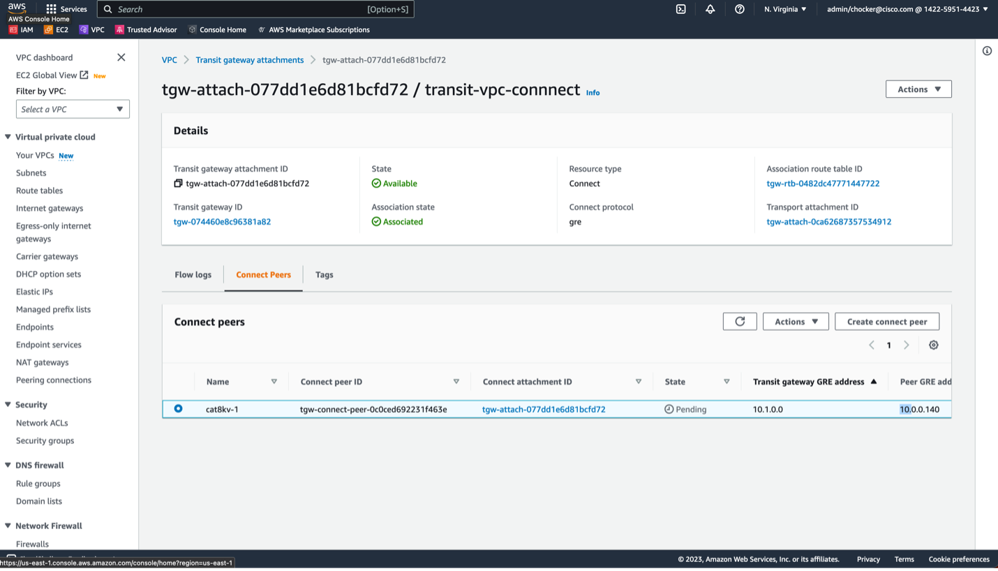
As with previous steps, it should eventually move from an initial state of Pending to Available. When Available you can move onto the next step.
If you scroll the peer to the right, you will see all the information needed to complete the configuration of the Cat8Kv. First, we need the GRE Tunnel information.
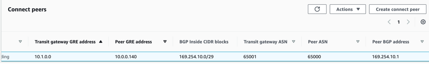
We also need the BGP peering information.
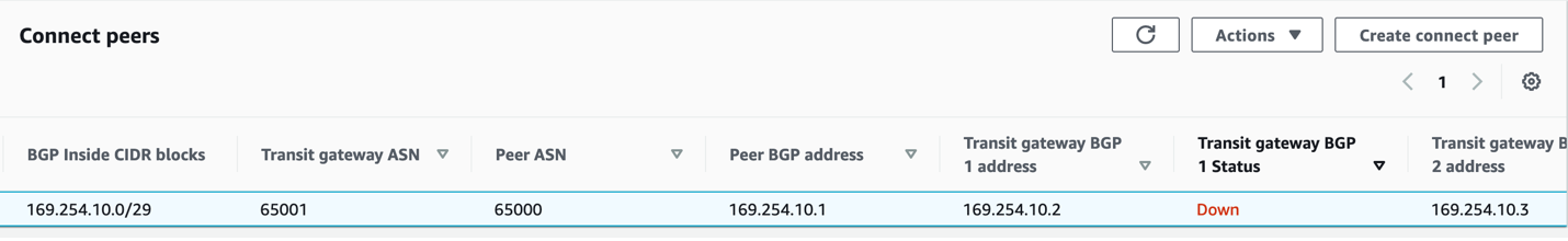
Notice that TGW has 2 BGP peer addresses. This provides a redundant control plane on the TGW.
Step 7: Configure Cat8Kv for TGW Connect Peering
In this section, we will configure the GRE tunnel and BGP neighbors on the Cat8Kv to complete the TGW connect peering.
- Login into the CLI of the Cat8Kv.
-
As a best practice, it is recommended to use the "front-door VRF" technique to separate the GRE tunnel transport from the GRE tunnel overlay routing. When you assign an interface to a VRF, it will remove the IP address, so you will need to apply it again. Please make sure you are not connected to the Cat8Kv over the interface you are applying the VRF or you will lose connectivity.
cat8kv-1#conf t Enter configuration commands, one per line. End with CNTL/Z. cat8kv-1(config)#vrf definition tgw cat8kv-1(config-vrf)#address-family ipv4 cat8kv-1(config-vrf-af)#int gig 2 cat8kv-1(config-if)#vrf forwarding tgw % Interface GigabitEthernet2 IPv4 disabled and address(es) removed due to enabling VRF tgw cat8kv-1(config-if)#ip address dhcp cat8kv-1(config-if)#end cat8kv-1#show ip int br Interface IP-Address OK? Method Status Protocol GigabitEthernet1 10.0.0.13 YES DHCP up up GigabitEthernet2 10.0.0.140 YES DHCP up up VirtualPortGroup0 192.168.35.101 YES TFTP up up -
Create the GRE Tunnel using the information from the create the connect peer step.
cat8kv-1#conf t Enter configuration commands, one per line. End with CNTL/Z. cat8kv-1(config)#inter cat8kv-1(config)#interface tunnel 1 cat8kv-1(config-if)#ip address 169.254.10.1 255.255.255.248 cat8kv-1(config-if)#tunnel source gig2 cat8kv-1(config-if)#tunnel vrf tgw cat8kv-1(config-if)#tunnel destination 10.1.0.0 cat8kv-1(config-if)#end -
Configure BGP neighbors to TGW.
cat8kv-1#conf t
Enter configuration commands, one per line.  End with CNTL/Z.
cat8kv-1(config)#router bgp 65000
cat8kv-1(config-router)#no bgp default ipv4-unicast
cat8kv-1(config-router)#neighbor 169.254.10.2 remote 65001
cat8kv-1(config-router)#neighbor 169.254.10.2 ebgp-multihop 2
cat8kv-1(config-router)#neighbor 169.254.10.3 remote 65001
cat8kv-1(config-router)#neighbor 169.254.10.3 ebgp-multihop 2
cat8kv-1(config-router)#address-family ipv4
cat8kv-1(config-router-af)#neighbor 169.254.10.2 activate
cat8kv-1(config-router-af)#neighbor 169.254.10.3 activate
cat8kv-1(config-router-af)#end
Note: When using EBGP between the Cat8Kv and TGW, ebgp-multihop 2 is required for the BGP peering to come up.
-
Verify BGP Neighbors are up.
cat8kv-1#show bgp ipv4 unicast summ
BGP router identifier 169.254.10.1, local AS number 65000
BGP table version is 2, main routing table version 2
1 network entries using 248 bytes of memory
2 path entries using 272 bytes of memory
1/1 BGP path/bestpath attribute entries using 296 bytes of memory
1 BGP AS-PATH entries using 24 bytes of memory
0 BGP route-map cache entries using 0 bytes of memory
0 BGP filter-list cache entries using 0 bytes of memory
BGP using 840 total bytes of memory
BGP activity 1/0 prefixes, 2/0 paths, scan interval 60 secs
1 networks peaked at 17:17:51 May 16 2023 UTC (00:02:21.080 ago)
Neighbor        V           AS MsgRcvd MsgSent   TblVer  InQ OutQ Up/Down  State/PfxRcd
169.254.10.2    4        65001      16      16        2    0    0 00:02:08        1
169.254.10.3    4        65001      18      19        2    0    0 00:02:21        1
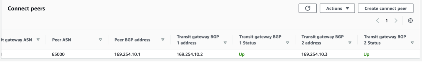
On the AWS console, it looks like this.
Notes
Troubleshooting
Note: For troubleshooting, at this time it does not seem you can ping the TGW GRE peer address (10.1.0.0 in the above example), but you can ping the BGP neighbor addresses for the TGW.
    cat8kv-1#ping vrf tgw 10.1.0.0
    Type escape sequence to abort.
    Sending 5, 100-byte ICMP Echos to 10.1.0.0, timeout is 2 seconds:
    .....
    Success rate is 0 percent (0/5)
    cat8kv-1#ping 169.254.10.2
    Type escape sequence to abort.
    Sending 5, 100-byte ICMP Echos to 169.254.10.2, timeout is 2 seconds:
    !!!!!
    Success rate is 100 percent (5/5), round-trip min/avg/max = 1/1/2 ms
    cat8kv-1#ping 169.254.10.3
    Type escape sequence to abort.
    Sending 5, 100-byte ICMP Echos to 169.254.10.3, timeout is 2 seconds:
    !!!!!
    Success rate is 100 percent (5/5), round-trip min/avg/max = 1/1/2 ms
Deploying Additional Cat8Kvs
As mentioned previously, it is recommended to deploy additional Cat8Kvs to provide redundancy and increased performance via scale out designs. It would generally be advised to use multiple availability zones for the redundancy requirement.
When configuring TGW Connect for the additional Cat8Ks, there are 2 options. 1. Use an existing TGW connect attachment and add another Connect Peer. Up to 4 peers per connect attachment are allowed. 2. Create another TGW Connect Attachment and add the Connect Peer to this new attachment.
Segmentation Between the Cat8Kv and TGW
It is possible to configure multiple tunnels between a single Cat8Kv and TGW and associate them with different route tables on each end. This allows to extend VRF segmentation from the on-prem network into the TGW.
WAN Integration to the Cat8K
WAN integration with the Transit VPC and the Cat8Ks is beyond the scope of this document. Generally, you will configure an IPSec tunnel between the Cat8Ks and the on-prem environment, using either the internet or a direct connect private peering as the transport.
BGP Policy on the Cat8Kv
It is beyond the scope of this document to discuss the details of the BGP policy that should be applied on the Cat8Kv for the TGW peers, but these are some considerations.
- As mentioned previously, the TGW only supports 1,000 routes over the TGW connect attachment peer. It may be required to summarize or filter routes to the TGW. Depending on the redundancy and traffic engineering requirements, it may be possible to send just a default route to the TGW from the Cat8Kv.
- If you have multiple Cat8Kvs and certain Cat8Kvs have different types of WAN connectivity or have difference levels of preference, it is possible to use traffic engineering via AS path prepending to influence the traffic paths from the TGW to the Cat8Kvs.
- If you have multiple Cat8Kvs and you would like to leverage ECMP load balancing, then the ASN and AS Path must be the same. See the AWS TGW connect attachment documentation for more information.
MTU
Information about the TGW MTU can be found here at the bottom. AWS Transit Gateway Quotas
It is probably recommended to increase the MTU on the Gigabit Ethernet interfaces used for TGW connect attachment to 8500 bytes, as done in this example. You may also need to configure the WAN interface and WAN tunnels to match the WAN MTU. It is likely the WAN MTU and TGW MTU will not match, so you will need to use features like 'ip tcp adjust-mss' to minimize fragmentation.
Licensing
You will need to acquire and license the Cat8Kv for production uses. Please see the Cisco documentation on options for licensing the Cat8Kv.
References
Deploying Cisco Catalyst 8000V Edge Software on Amazon Web Services