Cisco Catalyst 8000V Layer 2 Extension Lab
Overview
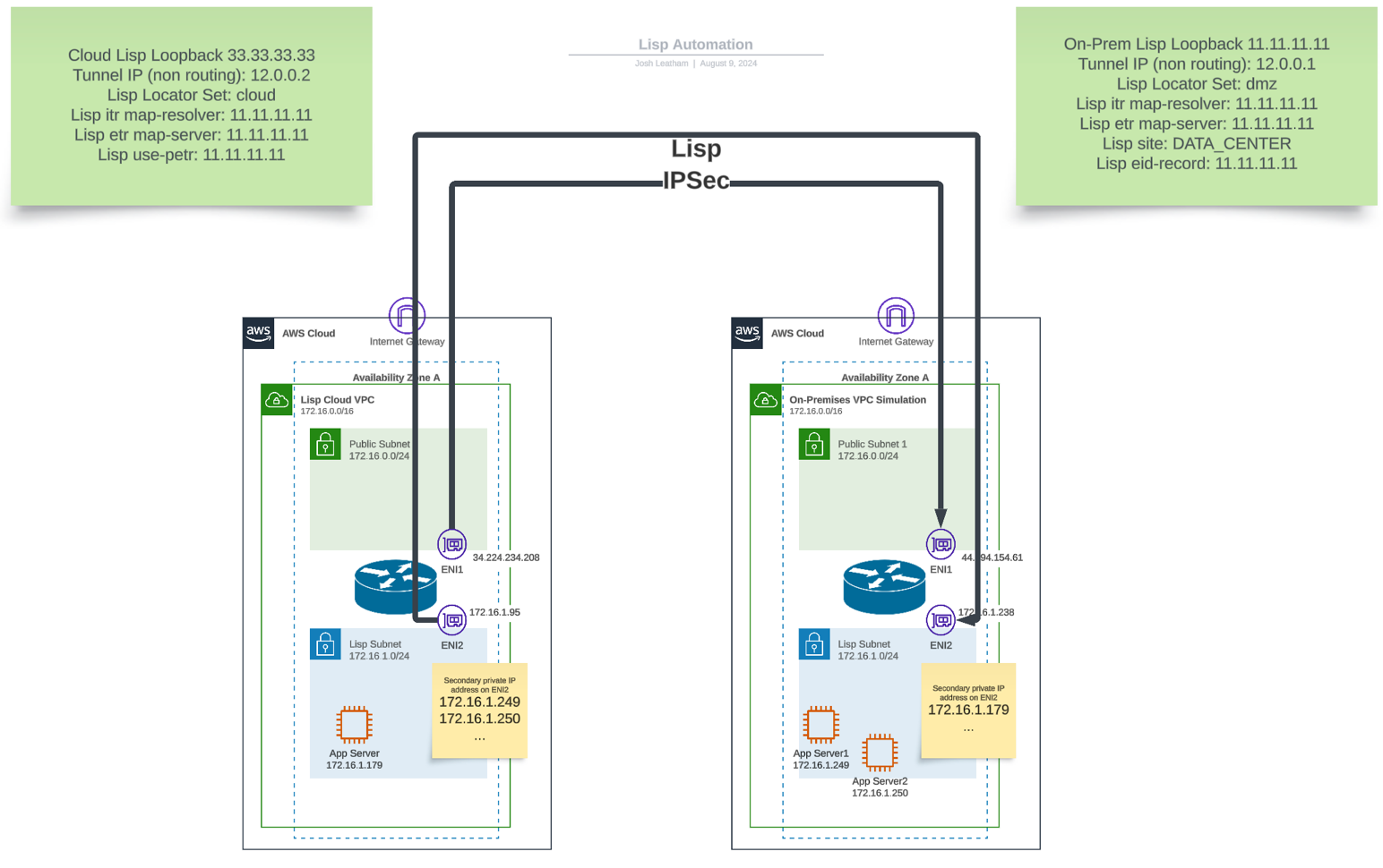
This lab demonstrates how to create Layer 2 Extensions (L2E) between on-premises networks and AWS VPCs using Cisco Catalyst 8000V virtual appliances. Layer 2 Extensions allow a single network subnet or broadcast domain to be extended across two disconnected network segments, enabling seamless migration of workloads without IP address changes.
Lab Architecture
In this lab, we will: - Deploy two Cisco Catalyst 8000V routers using CloudFormation templates - Configure LISP (Locator/ID Separation Protocol) for Layer 2 extension - Establish IPSec tunnels between the routers - Test end-to-end connectivity between extended networks
Architecture Note
The diagram shows a second App server that is not deployed in the template. This is for illustration only. As many servers as needed can be added based on ENI secondary IP limits.
Prerequisites
Before starting this lab, ensure you have:
- An AWS account with appropriate permissions
- Access to the AWS Management Console
- Basic understanding of networking concepts
- Familiarity with Cisco IOS XE CLI (helpful but not required)
Required AWS Marketplace Subscription
You must subscribe to the Cisco Catalyst 8000V BYOL AMI in the AWS Marketplace before proceeding:
- Navigate to AWS Marketplace
- Search for "Cisco Catalyst 8000V Edge Software"
- Subscribe to the BYOL (Bring Your Own License) version
- Accept the terms and conditions
Lab Components
This lab includes two CloudFormation templates:
- L2E-lisp-cloud-vpc-v3.yaml: Creates the cloud-side infrastructure
- L2E-lisp-on-prem-vpc-v3.yaml: Creates the simulated on-premises infrastructure
Download Templates
Click on the template names above to download the CloudFormation templates to your local machine before proceeding with the lab.
Step 1: Deploy the Cloud Infrastructure
We'll start by deploying the cloud-side infrastructure using CloudFormation.
1.1 Launch the Cloud CloudFormation Template
- Download the L2E-lisp-cloud-vpc-v3.yaml template
- Navigate to the AWS CloudFormation console
- Ensure you're in the us-east-1 region
- Click Create stack → With new resources (standard)
- Choose Upload a template file
- Upload the downloaded
L2E-lisp-cloud-vpc-v3.yamltemplate - Click Next
1.2 Configure Stack Parameters
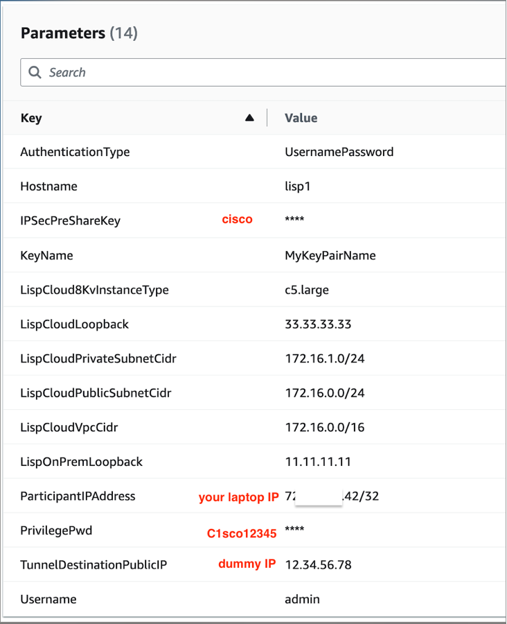
Configure the following parameters:
- Stack name:
lisp-cloud-infrastructure - TunnelDestinationPublicIp: Enter a dummy IP address (e.g.,
1.1.1.1) - We'll update this later with the actual on-premises router public IP
- Leave other parameters at their default values
Dummy IP Address
Use any public IP address as a placeholder. We'll update this after deploying the on-premises infrastructure.
1.3 Complete Stack Creation
- Click Next through the remaining screens
- Acknowledge the IAM capabilities checkbox
- Click Create stack
- Wait for the stack to reach CREATE_COMPLETE status
1.4 Record the Cloud Router Public IP
Once the stack is complete, note the cloud router's public IP address from the outputs:
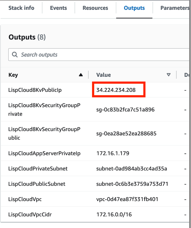
Save This IP
You'll need this IP address for configuring the on-premises router in the next step.
Step 2: Deploy the On-Premises Infrastructure
Now we'll deploy the simulated on-premises infrastructure.
2.1 Launch the On-Premises CloudFormation Template
- Download the L2E-lisp-on-prem-vpc-v3.yaml template
- Create a new CloudFormation stack
- Upload the downloaded
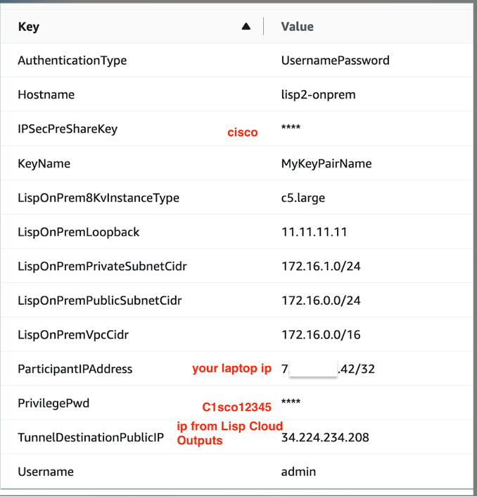
L2E-lisp-on-prem-vpc-v3.yamltemplate - Configure parameters:
- Stack name:
lisp-onprem-infrastructure - TunnelDestinationPublicIp: Enter the cloud router's public IP from Step 1.4
- Leave other parameters at defaults
2.2 Complete Stack Creation
- Click through to create the stack
- Wait for CREATE_COMPLETE status
2.3 Record the On-Premises Router Public IP
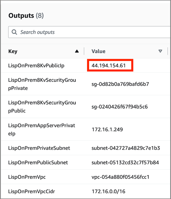
Note the on-premises router's public IP address from the outputs.
Step 3: Update Cloud Router Configuration
Now we need to update the cloud router with the correct on-premises router IP address.
3.1 Connect to the Cloud Router
Using SSH, connect to the cloud router:
If you used admin/pass instead of keypair, on your local laptop use:
ssh admin@<CLOUD_ROUTER_PUBLIC_IP>
When prompted for a password, use the default password from the CloudFormation template.
If you used a keypair, then you will login this way:
ssh -i "~/<PATH-TO-PEM>.pem" -o PubkeyAcceptedKeyTypes=+ssh-rsa ec2-user@<CLOUD_ROUTER_PUBLIC_IP>
The -o option might not be needed depending on the 8000v image in use.
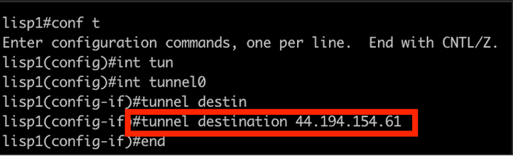
3.2 Update Tunnel Destination
conf t
int tunnel0
tunnel destination <ON_PREM_ROUTER_PUBLIC_IP>
end
Replace <ON_PREM_ROUTER_PUBLIC_IP> with the IP address from Step 2.3.
3.3 Verify Connectivity
Check that the connections are established:
show crypto ipsec sa
show ip ospf neighbors
show ip lisp map-cache
You should see: - IPSec SA established - OSPF neighbor relationship up - LISP map-cache populated
Step 4: Verify Protocol Status
4.1 Check IPSec Tunnel Status
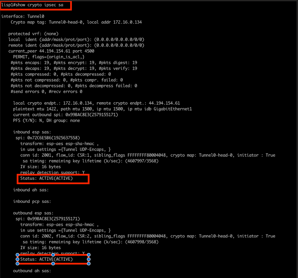
The IPSec tunnel should be up and passing traffic.
4.2 Verify OSPF Neighbors
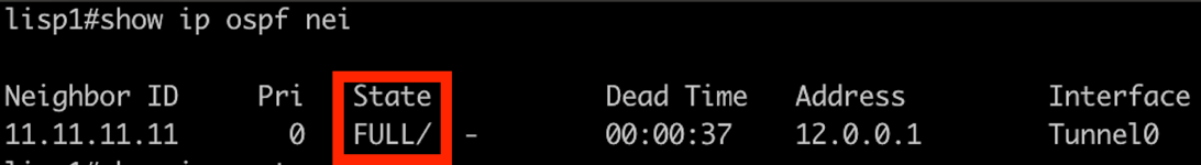
OSPF should establish neighbor relationships between the routers.
4.3 Check LISP Map-Cache
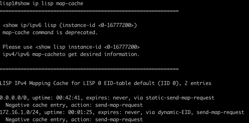
The LISP map-cache should show registered endpoints.
Step 5: Configure Layer 2 Extension
To enable Layer 2 extension between the networks, we need to add secondary IP addresses to the router interfaces.
5.1 Add Secondary IPs to Cloud Router
In the AWS Console, navigate to EC2 → Network Interfaces and find the private interface for the cloud router:
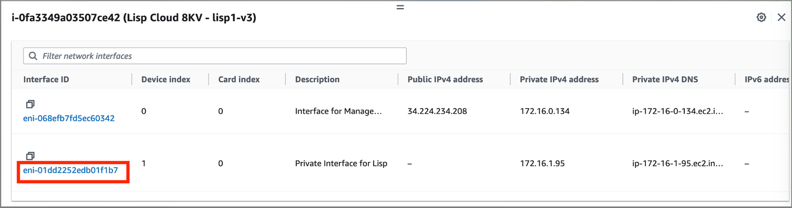
- Select the private network interface of the
Cloud router -
Click Actions → Manage IP addresses
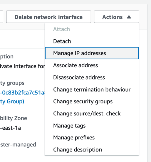
-
Add a secondary IP address that matches the on-premises app server subnet. Find this in the Cloud Formations Output of the
On-PremCFN deployment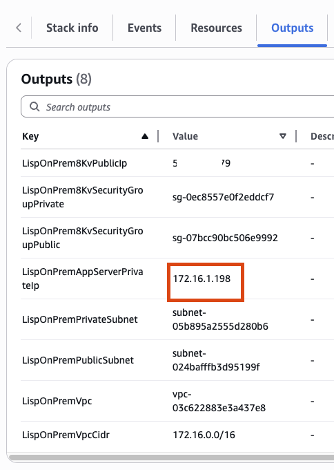
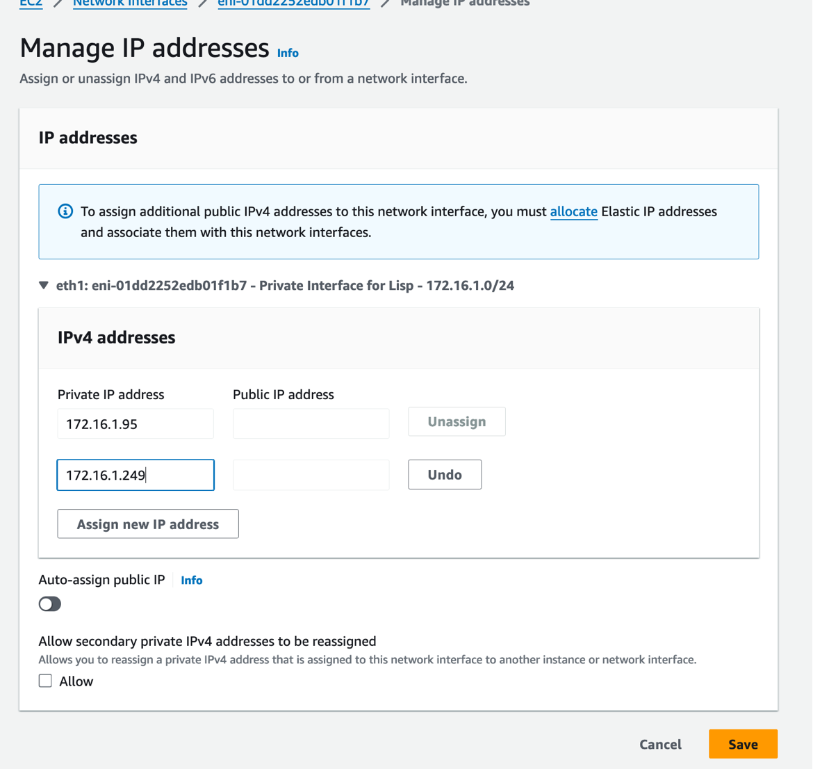
-
Save the changes
5.2 Add Secondary IPs to On-Premises Router
Repeat the same process for the On-Prem router:
- Find the private network interface of the on-premises router
-
Add a secondary IP address that matches the cloud app server subnet. Find this in the Cloud Formations Output of the
CloudCFN deployment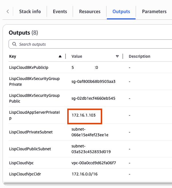
IP Address Planning
Each router needs a secondary IP address in the opposite network's subnet to enable Layer 2 extension. This must be done manually for each server that requires connectivity.
Step 6: Test End-to-End Connectivity
LISP Map-Cache Troubleshooting
If LISP IPs are not auto-installing in the database and connectivity tests fail, you may need to manually clear the LISP map-cache and initiate traffic in the correct direction.
6.1 Troubleshoot LISP Map-Cache (If Needed)
If you encounter connectivity issues where pings fail between the application servers, the LISP database may not be properly populated. Follow these steps to resolve:
- Clear the LISP map-cache on the cloud router:
SSH into the cloud router and run:
cisco
   clear ip lisp map-cache
- Initiate traffic from cloud to on-premises:
Use AWS Systems Manager Session Manager to connect to the cloud application server, then ping the on-premises application server:
bash
   ping <ON_PREM_APP_SERVER_IP>
!!! important "Traffic Direction Matters" It's critical to initiate the ping from the cloud to on-premises direction. This triggers the proper LISP registration process.
- Verify LISP map-cache installation:
On either the cloud or on-premises router, verify that the /32 host IPs are now installed:
cisco
   show ip lisp map-cache
You should now see the individual /32 IP addresses registered in the LISP map-cache.
6.2 Connect to Application Servers
Use AWS Systems Manager Session Manager to connect to the application servers deployed by the CloudFormation templates.
6.3 Test Connectivity
From the cloud application server, test connectivity to the on-premises application server:
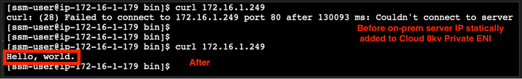
curl http://<ON_PREM_APP_SERVER_IP>
You should receive a successful HTTP response, demonstrating that Layer 2 extension is working.
6.4 Verify LISP Database Updates
Check both routers to confirm the LISP database is being updated with endpoint information:
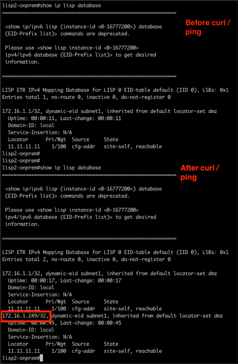
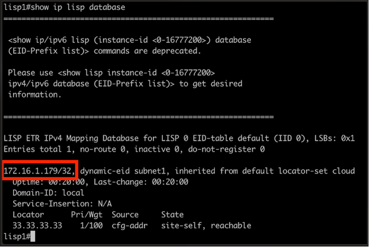
The LISP database should show registered endpoints from both sides of the connection.
Understanding the Solution
Layer 2 Extension Benefits
Layer 2 Extensions provide several key benefits:
- Seamless Migration: Applications can be moved without IP address changes
- Reduced Downtime: Minimize migration windows and application disruption
- Legacy Application Support: Supports older applications with hardcoded IP addresses
- Gradual Migration: Enables phased migration approaches
LISP Protocol Overview
LISP (Locator/ID Separation Protocol) separates endpoint identifiers from their network location:
- Endpoint Identifiers (EIDs): Identify hosts and subnets
- Routing Locators (RLOCs): Identify router attachment points
- Map-Server/Map-Resolver: Provides EID-to-RLOC mapping services
Network Components
The solution includes:
- Cisco Catalyst 8000V: Virtual router appliances
- IPSec Tunnels: Secure communication between sites
- OSPF: Dynamic routing protocol
- LISP: Provides Layer 2 extension capability
Troubleshooting
Common Issues
IPSec Tunnel Not Establishing - Verify security group rules allow IPSec traffic (UDP 500, 4500) - Check that public IP addresses are correctly configured - Confirm PSK (Pre-Shared Key) matches on both sides
OSPF Neighbors Not Forming - Verify IPSec tunnel is up first - Check OSPF network statements and area configuration - Ensure router IDs don't conflict
LISP Not Working - Confirm LISP is enabled on interfaces - Verify EID prefix configuration - Check map-server/map-resolver configuration
Diagnostic Commands
Useful commands for troubleshooting:
show crypto ipsec sa
show ip ospf neighbors
show ip lisp map-cache
show ip lisp database
show interface tunnel0
show ip route
Cleanup
To avoid ongoing charges, delete the CloudFormation stacks when finished:
- Delete the on-premises stack first
- Then delete the cloud stack
- Verify all resources have been removed
Conclusion
This lab demonstrated how to implement Layer 2 Extensions using Cisco Catalyst 8000V routers and LISP protocol. The solution enables seamless network extension between on-premises and AWS environments, supporting migration scenarios where IP address preservation is critical.
Key takeaways: - Layer 2 Extensions solve critical migration challenges - LISP provides scalable network extension capabilities - Cisco Catalyst 8000V offers enterprise-grade virtual routing - Proper planning and testing are essential for production deployments